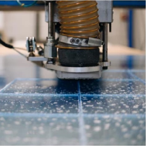
Converting clear PET sheet into controlled components

PET Sheet Fabrication Guide: Cutting, Printing and Thermoforming

PET sheet fabrication converts flat or roll-fed polyester sheet into cut blanks, printed components, folding parts, trays, clamshells and clear protective pieces. A reliable route begins by identifying the exact PET construction, then coordinating cutting, print, heat history, forming, trim, inspection and surface protection around the finished part.

Clear PET sheet being converted into a fabricated component
MaterialPET sheet, with APET as the main clear forming form
Core processesConvert, cut, print, form, trim and inspect
Quality focusClarity, registration, wall distribution and clean edges

Project logic

Make the process fit the product.

01

Specify the PET construction before selecting a process

PET names a polymer family, not a complete fabrication specification. Clear amorphous PET, commonly called APET, is widely used where clarity and thermoformability matter. PETG is glycol-modified and behaves differently during forming and joining. RPET introduces recycled content and may need additional appearance and batch-consistency controls. Multilayer structures can add sealing or forming functions that a monolayer sheet does not have. The drawing should identify the grade or approved material reference, roll or sheet format, nominal thickness, treated or printable face, protective film, cosmetic side and intended forming route. Any chemical, food-contact, recycled-content, flame, antistatic or other regulatory requirement must be tied to grade-specific documents and the finished application; it cannot be inferred from the word PET.

02

Build the operation sequence around the finished component

A practical route starts with material and visible-side approval, converts the roll or large sheet into manageable blanks, adds flat features in the correct sequence, forms the sheet when three-dimensional geometry is required, trims or drills the final interfaces, and then inspects and protects the part. The sequence changes with the product. A folding box may be printed and die cut while flat before creasing and folding. A clear tray is normally formed and then trimmed to a defined flange datum. A printed formed part needs a registration study because the artwork moves and stretches with the sheet. Drawings should therefore identify flat-sheet datums and finished-part datums where relevant rather than treating printing, forming and trim as unrelated jobs.

03

Match cutting and blanking to thickness, geometry and edge condition

Slitting and sheeting establish the starting blank. Punching or die cutting can add outlines, windows, tabs and score features to suitable thin sheet, while sawing and routing are practical for thicker panels, shaped profiles and repeatable trim geometry. Tool condition, backup support and complete penetration matter because a partial or ragged cut leaves notches that can propagate during folding, forming or handling. Sharp tools, stable support and effective chip removal also protect a clear face from vibration marks and trapped swarf. A fused edge, smeared chip, rough notch or discoloured zone is process evidence: review tool geometry, sharpness, feed, support and heat control instead of accepting the defect and adding an undefined finishing operation.

04

Plan CNC routing and drilling around heat, chips and assembly stress

CNC routing can make profiles, slots, pockets and trim features when workholding supports the sheet and the toolpath controls entry, exit and small unsupported details. Chips must be cleared without dragging across the cosmetic face. Drilled holes should be smooth and free from rough exit damage; deep holes may need chip withdrawal and material-approved cooling. Metalworking fluids should never be assumed compatible with PET. Hole location, surrounding material, head style, assembly clearance and thermal movement should be reviewed together, and fasteners should not be used to pull a misaligned sheet into position. Manufacturer drill angles or edge distances apply only where the published material and conditions match the job, so production drawings should rely on a verified sheet-specific rule rather than a copied generic number.

05

Treat PET laser cutting as a qualified route, not a default

Laser cutting may create intricate profiles, but PET suitability is both a safety and an edge-quality question. Brett Martin's Marpet guide warns that laser cutting its aPET and PETg sheets produces noxious gases, requires effective extraction and can leave roughness or discoloration. ONE PLASTIC has general plastic laser-cutting capability, but a PET job should use that route only after the exact sheet, thickness, equipment, extraction, edge standard and post-process condition have been reviewed. Routing, die cutting or another mechanical method should remain the documented alternative when those conditions are not confirmed. A sample must represent the production material and real profile, not merely prove that a laser can penetrate a small coupon.

06

Qualify printing as a material, surface and ink system

PET can be screen or digitally printed when its surface and the ink system are compatible. Printable PET should still identify which side is treated or coated. Toray's Lumirror PA26, for example, is a PET film designed with different sealing and print-receptive faces; it demonstrates why both faces of every clear sheet cannot be assumed equivalent. Before printing, define the viewing side, artwork orientation, white layer, cut or fold datum and later conversion steps. Approval should use production sheet and should check color, opacity, adhesion, abrasion and registration after the downstream operation. A print that looks correct while flat may crack, stretch or shift after creasing or forming, so printed formed parts require a representative conversion trial.

07

Control PET thermoforming through heat history and geometry

Thermoforming heats a clamped sheet, shapes it by vacuum, pressure or mechanical assistance, cools it and removes the trim. PET rigid-film manufacturers document PET for trays, containers, clamshells and liners, but the operating window remains construction-specific. For clear APET, even heating and timely cooling are central controls: excessive or poorly controlled heating can promote crystallisation and whitening, while release before sufficient cooling can distort the part. Review draw depth, radii, draft, flange width, venting, clamp area, part spacing, trim datum and cooling as one system. Deep draws, narrow channels, visible walls, printed graphics and critical mating features deserve a representative trial that checks clarity, wall distribution, release and the final trimmed interface.

08

Keep joining, finishing and cleaning within verified boundaries

APET may be difficult to bond reliably. For its Marpet-a FS product, Brett Martin recommends considering adhesive tape, mechanical fastening or welding and requires compatibility testing for adhesives. That guidance does not prove that every joining route is available or suitable for every ONE PLASTIC PET project. Any tape, adhesive or welding method should therefore define surface preparation, load direction, bond area, cure or dwell condition and an acceptance test before it enters the production specification. Edge finishing should remove dangerous burrs and notches, but an acrylic-style polished optical edge should not be promised unless a PET sample proves the appearance and durability. Cleaning agents likewise need confirmation for the selected sheet, especially where machining or forming has introduced stress.

09

Inspect each operation by its function and read defects as evidence

Incoming inspection should confirm the material reference, thickness plan, surface treatment, protective film and roll or sheet condition. After cutting, check profile, notches, heat damage and scratches. After printing, verify orientation, adhesion, cure, abrasion and registration. After forming, inspect clarity, whitening, wall distribution, webbing, detail, release marks and distortion after cooling. Final trim and drilling checks cover datums, flange condition, holes and mating features; packing checks cover cleanliness, orientation, interleaving and protection from face-to-face rubbing. White formed areas point toward heat history, cracks near holes toward notches or forced assembly, lifted ink toward a surface-ink mismatch, and thin corners toward draw distribution. The technical basis includes Brett Martin, Toray and Klöckner Pentaplast manufacturer guidance, but their product-specific parameters never replace the current data sheet and trial for the actual production sheet.

Applications

Where this route creates value.

01Thermoformed trays and inserts
02Clear folding-box components
03Printed PET panels and blanks
04Clamshell and blister components
05Die-cut packaging parts
06Clear protective and display pieces

Common questions

Details buyers ask before an RFQ.

Is APET the same as PETG?+

No. Both are polyesters, but PETG is glycol-modified and can behave differently in forming, joining and fabrication. The approved grade name should appear on the drawing.

Can PET sheet be CNC routed?+

PET sheet can be routed or milled when tooling, support, chip removal and heat control are qualified for the selected sheet and geometry.

Can PET sheet be laser cut?+

Some PET sheets can be laser cut, but it is not a default route. Material suitability, fumes and extraction, edge discoloration, thickness and post-process condition require a documented trial and safety review.

Can PET sheet be printed before thermoforming?+

It may be possible with compatible sheet and ink, but adhesion, heat exposure, stretching and registration must be tested on a representative formed part.

Does APET always need pre-drying before forming?+

No universal rule should be used. Follow the current technical guide for the selected construction and account for its storage history before deciding whether conditioning is required.

What should a PET fabrication drawing include?+

Identify the material reference, thickness, visible side, print side and orientation, flat and finished datums, cut and formed geometry, mating features, cosmetic zones and inspection priorities.