Engineering PMMA sheet into finished components

Custom Acrylic Sheet Fabrication Guide

Acrylic sheet fabrication converts flat PMMA sheet into clear covers, display panels, enclosures, signs, boxes and other functional components. The result depends on more than the cutting machine: sheet grade, visible surfaces, hole and corner design, forming sequence, joint preparation, edge finish, residual stress and protective handling all influence the finished part.

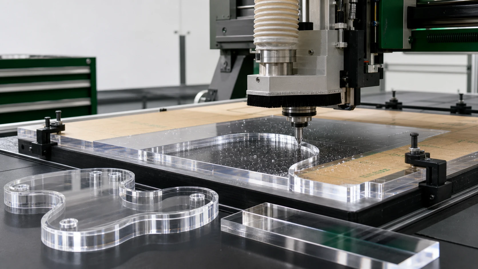
Acrylic sheet being cut for a fabricated component
MaterialAcrylic / PMMA sheet
Core processesCut, CNC, drill, form, bond and polish
Quality focusClarity, edge finish, fit and stress control

Project logic

Make the process fit the product.

01

Begin with material behavior and the visible surfaces

PMMA is commonly called acrylic or acrylic glass, but acrylic sheet is not one uniform starting material. Clear, colored, cast and extruded constructions can behave differently during machining, forming and bonding. The drawing should therefore name the selected sheet and identify which faces and edges will remain visible. A polished display edge, a hidden mounting edge and a bond-preparation edge do not require the same route. Surface masking normally stays in place through compatible cutting and machining operations, while forming may require it to be removed before heating. That decision should follow the sheet manufacturer's guidance. Clean work surfaces, non-marking fixtures and part separation are basic process controls because damage that is minor on an opaque plastic can be immediately visible on a transparent acrylic component.

02

Choose a cutting method by geometry and edge requirement

Sawing, CNC routing and laser cutting can all separate acrylic sheet, but they leave different edge conditions and suit different geometry. Sawing is efficient for sheet breakdown and straight panels when the sheet is fully supported and the blade, feed and heat are controlled. CNC routing is useful for repeatable profiles, pockets, slots and internal features, and it gives the programmer control over entry points, holding areas and later finishing allowances. Laser cutting can create detailed two-dimensional profiles and a glossy edge on suitable acrylic, but the result depends on grade, thickness, color, focus and feed. A rough, fused, dull or heavily striated edge is evidence that the route needs adjustment. Polishing should not be used automatically to hide an unstable cutting process.

03

Plan CNC routing around workholding, heat and chip removal

A CNC router can produce accurate profiles, cutouts, pockets, bores and engraved details, but acrylic needs a process designed for plastic rather than copied from metal machining. Excess heat can soften the cut and redeposit material; unstable workholding can create vibration, chipping or dimensional variation; trapped chips can scratch the visible surface. The toolpath should consider where the cutter enters and exits, how narrow bridges and small islands remain supported, and which edges will later be polished or bonded. The drawing should identify datum edges and critical interfaces so inspection relates to assembly function. Exact speeds and feeds are not universal values: they depend on the selected grade, thickness, cutter geometry, spindle, fixture and depth of cut and should be verified on representative material.

04

Design holes, cutouts and corners to manage stress

Holes and internal corners deserve the same engineering attention as the outside profile. A hole close to an edge, a sharp internal corner, an unsupported narrow bridge or a forced fastener alignment can concentrate stress. PMMA may retain residual stress from machining, forming or assembly, and the effect can remain hidden until the part is loaded or exposed to an incompatible cleaner, adhesive or other chemical. Where the design allows, use intentional radii, provide appropriate edge distance and avoid using fasteners to pull a misaligned part into position. Support the sheet on a firm, clean base during drilling and define any countersink, counterbore or threaded feature explicitly. Fine cracks or a whitish crazed area should trigger a review of geometry, machining quality, assembly load and chemical compatibility together.

05

Sequence heating and forming after the flat geometry is understood

Acrylic sheet can be line bent or thermoformed into curved covers, guards and dimensional components. The mold, jig or bending setup should be ready before heating, and the part needs to cool in the intended shape before it is evaluated. Heating can change hole position, printed graphics, cutout geometry and edge alignment, so the operation sequence should be decided during design review. A feature that crosses a bend may distort if it is produced at the wrong stage. Forming surfaces and handling tools must also protect the cosmetic face from marks. A representative trial is especially useful for tight geometry, visible curves and parts that must mate with another component. Check the cooled profile, trim datum and real interface rather than judging the part while it is still warm.

06

Treat bonding as a designed joint, not an adhesive afterthought

Clear acrylic boxes, guards, housings and display assemblies often use bonded joints, mechanical fasteners or both. The joining method should be selected with the load path, edge preparation, cleaning process and acceptable bond-line appearance. Bond surfaces need controlled fit and alignment; poor preparation can leave gaps, bubbles, contamination or visible excess adhesive. The adhesive must be compatible with the specific acrylic grade and the service environment, and handling should allow the joint to cure adequately before it is loaded. An instruction such as 'invisible bond' is not a measurable acceptance standard. Instead, define which side is viewed, the lighting or sample reference, allowable visual variation and the features that control alignment. A cosmetic display box and a concealed equipment enclosure can reasonably use different joint criteria.

07

Specify edge finishing only where it adds value

A cut acrylic edge may remain machined, be deburred, sanded, polished or prepared specifically for bonding. The correct finish depends on whether users see or touch the edge, whether it transmits light, whether it fits a frame, and whether it becomes part of a joint. Sanding and polishing can create a high-gloss result, but every extra finishing step adds handling and must preserve nearby surfaces and dimensions. A drawing that simply states 'polish all edges' can create unnecessary work while still failing to identify the truly important viewing edges. Mark the cosmetic edges, provide a visual reference when appearance is critical and keep bonding edges separate from purely decorative polishing requirements.

08

Build quality inspection into every operation

Acrylic quality is easier to control when inspection follows the process rather than waiting until packing. Before fabrication, verify sheet identity, color, finish, masking and visible-side marking. After cutting or routing, inspect profile, cutouts, edge condition and surface protection. After drilling, check feature position, burr removal and damage around holes. After forming, verify the cooled shape, trim datum, surface marks and mating interfaces. After bonding or assembly, inspect alignment, cleanliness, joint appearance and handling damage. The method should follow the feature's function: optical faces need controlled lighting and viewing criteria, interfaces need dimensional or fit checks, and formed components may need a fixture or profile reference. A generic 'visual inspection passed' statement does not demonstrate that the part will fit or perform.

09

Read common defects as process evidence

Scratches usually point to damaged masking, dirty fixtures, trapped chips or inadequate part separation. Fused or rough edges suggest a mismatch among cutting method, tooling, support, feed and heat. Cracks around holes and corners can indicate concentrated stress, poor edge condition or forced assembly. White haze or fine crazing after cleaning may reveal an interaction among residual stress, fastener load and chemical exposure rather than a polishing problem. Formed parts that do not fit often trace back to the wrong trim datum, cooling condition or interface reference. Visible bond-line variation can result from joint geometry, preparation, alignment or cure handling. Treating each symptom as evidence helps correct the route instead of adding a cosmetic rework step at the end.

10

Use manufacturer guidance with an explicit applicability boundary

The technical basis for this guide includes Röhm / PLEXIGLAS instructions for cutting, machining, drilling, bending and forming, bonding, and sanding and polishing. These are appropriate primary references for understanding PMMA processing principles, surface protection and defect signals. They are not a substitute for the technical data sheet of the exact sheet grade or for a production trial on the selected equipment. Published parameters should be used only when their material, thickness and process conditions match the job. When that boundary is unclear, the responsible approach is to define a representative trial, record the result and approve the part against its real functional and cosmetic requirements.

Applications

Where this route creates value.

01Transparent equipment covers
02Retail display panels
03Acrylic boxes and cases
04Sign faces and information panels
05Machine-viewing windows
06Bonded acrylic assemblies

Common questions

Details buyers ask before an RFQ.

Can acrylic sheet be CNC routed?+

Yes. Acrylic can be routed for profiles, cutouts, pockets and other features when tooling, workholding, heat control and chip removal are planned for the selected sheet and geometry.

Can acrylic sheet be laser cut?+

Suitable acrylic sheet can be laser cut for detailed profiles. Edge appearance depends on grade, thickness, color and process conditions, so visible parts should be verified with a representative sample.

Should protective film stay on during acrylic fabrication?+

It commonly remains during compatible cutting, routing and drilling operations. Forming or certain bonding steps may require removal; follow the selected sheet and process guidance.

Can acrylic sheet be bent or thermoformed?+

Yes. Molds or bending jigs, heating sequence, surface handling, cooling and later trimming should be planned for the specific part.

Why does acrylic crack around drilled holes?+

Possible causes include edge-near features, machining damage, sharp geometry, residual stress, forced fastener alignment or chemical exposure. The complete material-process-assembly route should be reviewed.

What causes white haze or crazing in acrylic?+

Fine crazing may result from residual or assembly stress interacting with an incompatible cleaner, adhesive or other chemical. It should not be treated only as a surface-polishing defect.

How should a polished acrylic edge be specified?+

Identify the visible edges, distinguish cosmetic polishing from deburring or bond preparation, and use an agreed sample or viewing reference when appearance is critical.